UPDATE 05.02.2026:
This project is no longer actively developed, as I simply do not have the time. However, user notownblues has made better than it ever was, fixing bugs, adding features, streamlining the flashing process and even developing a custom zones add-on!
This are the relevant repositories: SHS-Z2M-Presence & SHS-Z2M-Presence-Zones
DISLAIMER:
Building a DIY Zigbee sensor is not a simple task. It’s far more involved than just flashing an ESP32 with ESPHome, which is why custom Zigbee devices are relatively rare. While I did my best to ensure the sensor works properly and you can use it freely in your own smart home, there is always room for improvement and refinement.
Therefore, this project should not be considered a production-ready device. It is meant for tinkerers and enthusiasts as a learning resource, to be used as a base we can all build on and expand. SmartHomeScene’s content is free and always will be. If you want to support the site, you can always buy us a cup of coffee.
I welcome your feedback, suggestions, and experiences on how this project can be improved further. Please leave them in the comments below.
Intro and project requirements
A while back, Espressif released two mainstream IEEE 802.15.4 boards: ESP32-C6 and ESP32-H2. Which means, both of these support Zigbee and Thread, opening up the door to DIY Zigbee/Thread devices and making things a bit easier.


This DIY Zigbee presence sensor is based on the ESP32-C6-WROOM-1 and the Hi-Link HLK-LD2410C mmWave radar sensor. The firmware also works with the LD2410/LD2410B and can also be adapted to work with the latest HLK-LD2412 radar. Besides the board, this project requires the following things:
- HLK-LD2410C [AliExpress, Amazon]
- Dupont connectors [AliExpress, Amazon]
- Data cable (USB-C)
The firmware can also work with the ESP32-H2, although it requires changes and using different GPIO pins. Since I do not have one, I have not tested the sensor with the H2. Feel free to try and adapt it for the H2 and share your insights below.
Wiring and connection
The HLK-LD2410C radar communicates with the ESP32-C6 over UART. To connect it properly, you need power, ground and two data lines. This wiring ensures that the radar’s transmit line connects to the ESP32’s receive pin, and vice versa. The UART link runs at 256000 baud, which is supported by the ESP32-C6 hardware. These are the connections you will need to make:
- VCC (LD2410) → 5V (ESP32-C6)
- GND (LD2410) → GND (ESP32-C6)
- TX (LD2410) → GPIO4 (RX1) (ESP32-C6)
- RX (LD2410) → GPIO5 (TX1) (ESP32-C6)
The ESP32-C6 allows several pins to be assigned to UART, but GPIO4 and GPIO5 were selected because they provide the most stable and reliable option at the high baud rate of 256000. These two pins are hardware-mapped to UART1, so they handle continuous data streaming from the LD2410C without issues.
Unlike some other pins on the chip, they are not tied to bootstrapping functions, meaning the device always starts up cleanly even with the radar connected. They are also unused by other essential parts of the firmware, such as the Zigbee radio or the boot button on GPIO9, which further avoids conflicts. This makes GPIO4 and GPIO5 the safest and most robust choice for handling the radar’s data link.
Firmware overview and design logic
At its core, this project takes the LD2410C mmWave radar and makes it work as a simple, reliable Zigbee presence sensor. The radar itself can detect whether someone is moving or sitting still in a room, but the raw data it produces is messy and not very useful on its own. The firmware cleans this up and only sends the important states to Zigbee, so you get stable entities in Home Assistant that you can actually use for automations, without flooding your mesh network with useless payloads.
The way this is achieved is by combining a few building blocks inside the firmware: the radar data is read and smoothed out via UART, the information is mapped into Zigbee clusters so coordinators can understand it, and the boot button is given a smart role so you can reset everything easily if needed. That’s the simple view of things.
For those who want to dive deeper into the technical side, read below to learn how each part was implemented in more detail.
LD2410 data parsing and cooldown logic
The HLK-LD2410C radar streams detection frames over UART at 256000 baud. Each frame begins with the header bytes F4 F3 F2 F1, followed by a length field and a series of data blocks. In total, the LD2410 publishes several types of information:
- A state byte that signals whether a moving target, a static target, or both are detected
- Bit 0 = moving
- Bit 1 = static
- Bit 0 or Bit 1 = occupancy
- Energy levels for each detection gate, covering distances from around 0.75 m up to 6 m depending on the configured range
- Distance values for the closest moving and closest static target
- Signal strength and quality metrics describing the radar return
- Configuration echoes when parameters are updated
The firmware intentionally keeps things simple and only parses the state byte. This provides the moving, static, and combined occupancy states needed for reliable and immediate presence sensing. For the time being, I decided to not parse the rest of the data for the following reasons:
- Distance reporting would result in noisy, constantly changing values. If these were pushed to Zigbee, the device would flood the network too much, making it unreliable for real-world use.
- Energy levels per gate and signal strength metrics are skipped for the same reason. They may be useful for debugging, but they add little value for daily automations.
- Configuration echoes are ignored since the firmware itself manages and stores all parameters in NVS, so there is no need to re-process what was just sent.
For configuration, this firmware applies sensitivity and range values globally across all gates. Individual gate configuration is planned for a future firmware update, which will allow fine-tuning of detection at different distances, similar implementation like the Apollo MSR-2 Multisensor.
Finally, the firmware adds a firmware-defined movement cooldown layer on top of the raw state values. When the radar stops reporting motion, the moving state is kept active for a user-defined time before clearing. This prevents rapid toggling caused by brief detection gaps and creates a smoother, more stable presence signal. Setting the cooldown to zero disables it completely, although I suggest you do not do that. The sensor will jump very frequently from detected to clear, flooding the network.
Endpoints, clusters and attributes implementation
Once the LD2410C data is parsed, obviously it needs to be represented in a Zigbee-compliant way so Home Assistant and other controllers can understand at least the basic occupancy cluster. For this firmware, I designed a two-endpoint structure that keeps things simple but powerful.
Endpoint 1: Light and configuration
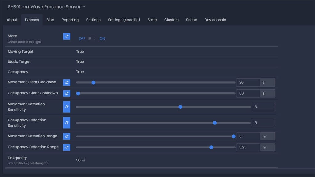
Endpoint 1 is defined as a standard HA On/Off Light device. This is primarily used to drive the onboard light driver, giving a straightforward binary switch that can be controlled from Zigbee2MQTT. While simple, it is useful for feedback, debugging, or even integration into automations as a visual indicator. To keep things simple and focus on presence detection, I purposefully removed RGB controls from the light.
Alongside the On/Off cluster, Endpoint 1 also hosts a custom configuration cluster at ID 0xFDCD. This cluster exposes several attributes that control how the radar operates:
- Movement cooldown (seconds)
- Occupancy clear duration (seconds)
- Moving sensitivity (0–10 proxy, internally 0–100)
- Static sensitivity (0–10 proxy, internally 0–100)
- Moving maximum gate (0–8, 0.75m step)
- Static maximum gate (2–8, 0.75m step)
The sensitivity sliders shown in Zigbee2MQTT range from 0–10 for convenience, but internally these values are mapped to the radar’s 0–100 scale. A value of 10 on the slider means maximum sensitivity (100), while 0 means the radar is effectively disabled for that detection type. This mapping keeps the interface simple while still allowing fine, granular control.
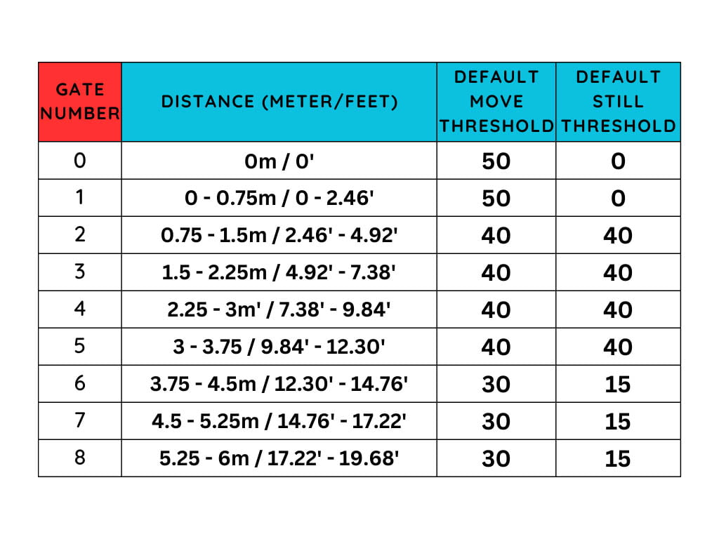
The gates define how the LD2410C splits its detection range into distance zones. Each gate represents a step of 0.75 meters.
Each gate also has a default energy threshold for detection. The firmware applies separate thresholds for moving and static targets, but controls them globally through the sensitivity sliders.
For moving detection, the maximum gate can be set from 0 to 8, covering the entire range. For static detection, the maximum gate starts at 2. This is because gates 0 and 1 are too close to the radar and often dominated by noise and reflections, making static presence unreliable. By starting from gate 2, static detection begins at 0.75 m and extends outward, where the radar can better distinguish a still target from background interference.
All of these attributes are read/write and are persisted in NVS so the device always restores the same behavior after a reboot. To avoid wearing out flash memory, updates are debounced, cooldown values are saved immediately, while sensitivities and gate changes are queued and written after 500 ms.
Endpoint 2: Occupancy sensing
Endpoint 2 uses the standard Occupancy Sensing cluster at ID 0x0406. Here, the device publishes three states as manufacturer-specific attributes:
- Moving target detected
- Static target detected
- Occupancy (either moving OR static)
These appear in Zigbee2MQTT and Home Assistant as clean binary entities. Because they use a standard cluster, the integration is seamless, while the custom attributes provide the extra detail not available in stock Zigbee presence sensors.
Why this design
This two-endpoint layout was chosen after experimenting with a five-endpoint version that separated moving, static, occupancy, light, and config. That design technically worked but cluttered the Zigbee2MQTT interface and created unnecessary complexity. I feel that this two-endpoint model strikes a balance between standards compliance and flexibility.
If you better a better suggestion on how to handle the endpoints, I’d love to hear it!
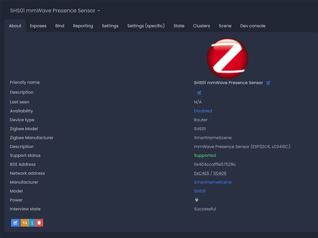
Zigbee device name and metadata
Besides the endpoint and cluster layout, the firmware also makes sure the device identifies itself correctly on the Zigbee network. This helps both Zigbee2MQTT and Home Assistant recognize it as a valid router and display useful information.
- Manufacturer name:
SmartHomeScene - Model identifier:
SHS01 - Date code: build date of the firmware (e.g.
2025-08-29) - Software build ID: semantic version of the firmware (e.g.
SHS01-1.0.0) - Power source: always reported as mains powered
- Network topology: Zigbee Router
The device name and model identifier can be changed in the shs01.h firmware file by adjusting the SHS_MANUFACTURER_NAME and SHS_MODEL_IDENTIFIER lines. These strings are defined as length-prefixed ASCII values (the first byte defines the number of characters that follow):
/* Manufacturer / Model strings for Basic cluster (length-prefixed ASCII) */
#define SHS_MANUFACTURER_NAME   "\x0E""SmartHomeScene"   // 0x0E = 14 characters
#define SHS_MODEL_IDENTIFIER    "\x05""SHS01"            // 0x05 = 5 characters
You would also need to change the model and vendor ID identifiers in the external converter, so the device is recognized properly in Zigbee2MQTT. These are found at line 126, under module.exports.
Boot button and factory reset behavior
A critical part of any Zigbee device is the ability to recover from misconfiguration or network issues without re-flashing firmware. For this reason, the boot button on the ESP32-C6 board was repurposed to handle reset/pairing logic.
When the button is pressed and held for six seconds, the device enters its factory reset routine:
This sequence performs three actions in order:
- Erase Zigbee network data so the device is returned to a factory-new state and can be paired again.
- Clear all configuration values in NVS, including cooldowns, sensitivities, and gate settings.
- Restart the device, so it immediately begins normal operation with default parameters.
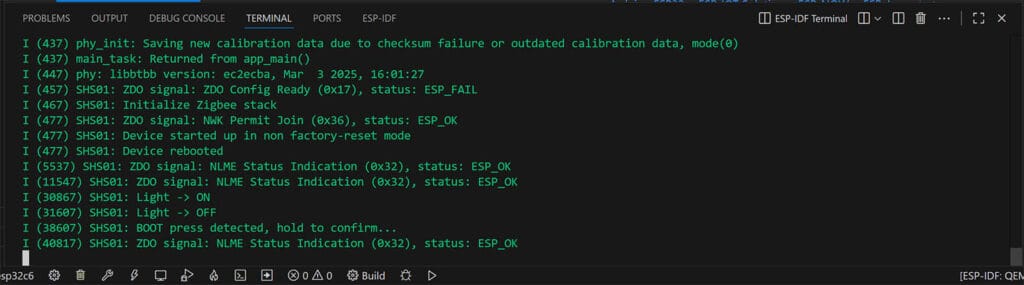
During the long-press, logs clearly announce that the reset is armed, and after the hold time expires, confirmation is shown that the reset is complete. This helps avoid accidental wipes when the button is tapped briefly. Always enter idf.py monitor when pairing the device and keep an eye on the logs:
Preparing the environment
There are many ways to build and flash firmware onto an ESP32-C6. You can use the command line, ESP-IDF directly, or even Espressif’s official flasher tools. For this project, I use Visual Studio Code (VS Code) with the ESP-IDF extension because it provides an integrated environment that is easier to manage. It allows you to install the SDK, handle dependencies, build the firmware, and monitor logs all in one place.
NOTE: Even though some of these instructions may seem obsolete or obvious, I am sharing them anyway so that less tech-savvy people can try it out as well.
Installing VS Code and ESP-IDF
- Install Visual Studio Code from the official website.
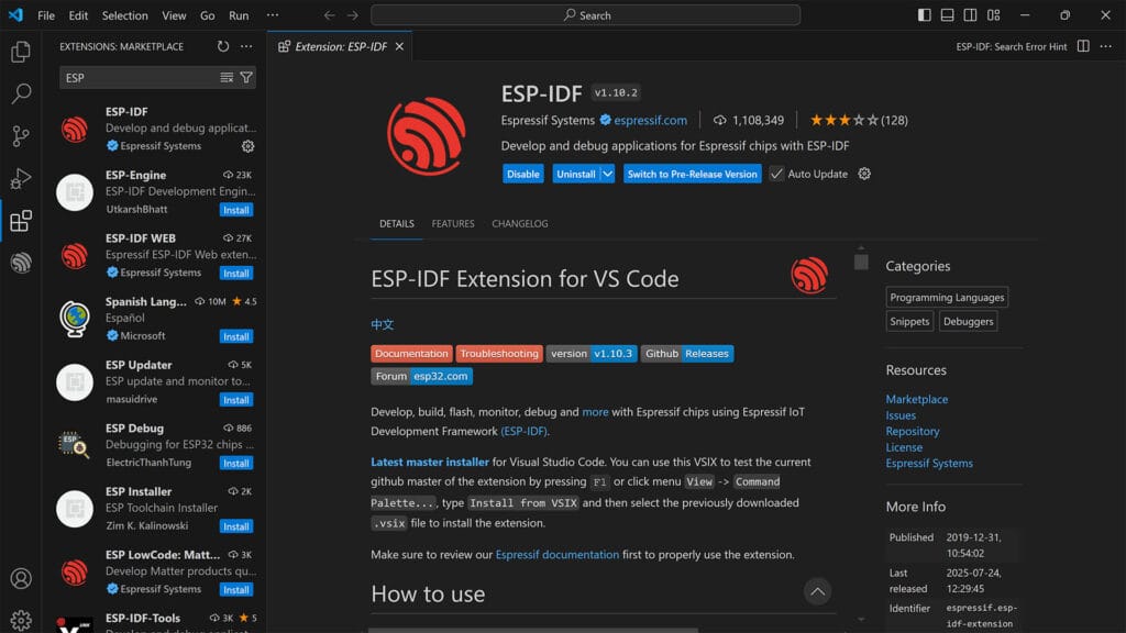
- Open VS Code and select Extensions from the left menu
- Find and install the ESP-IDF extension.
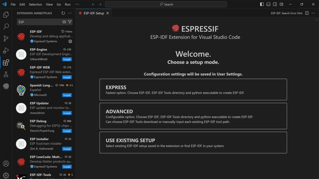
- When prompted, run the setup wizard and choose EXPRESS Installation
- You can also start the wizard by pressing Ctrl+Shift+P and searching ESP-IDF: Configure ESP-IDF extension
- You can also choose ADVANCED and change the directories
- From the dropdown, select the latest version (v.5.5.1 as of Sept, 2025)
- Press Install which will download and install:
- ESP-IDF SDK (v5.x or newer for ESP32-C6)
- The toolchain for RISC-V targets
- Python with pip for dependencies
- CMake, Ninja, and Git
- The process takes about 20 minutes, so be patient
- Done!
Connecting the board and finding the port
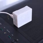
The next step is to connect the board to your PC. Use a USB-C data cable plugged into the left USB-C port marked “CH343” (this is the onboard USB-to-UART chip). Do not use the right USB-C port, which is reserved for native ESP32-C6 functions. Once attached, find the correct port and remember it:
- Windows: Device Manager > Ports (COM & LPT) > USB-Serial CH343 (COMx)
- Mac:
ls /dev/tty.*→ look for /dev/tty.usbserial-xxxx - Linux:
dmesg | grep tty→ check for /dev/ttyUSBx
Building and flashing the firmware
Once you have the port number (e.g. COM4), you are ready to build and flash.
- Download the .zip file containing the project
- Extract the .zip on your computer
- Open VS code, click File > Open Folder and select the
SHS01folder - Press CTRL + Shift + P and Search for ESP-IDF: Open ESP-IDF Terminal
- Execute the following commands, in order to build and flash the firmware
Set target to esp32c6. Alternatively, select it manually in the bottom left corner (CPU icon):
idf.py set-target esp32c6Build the project
idf.py buildFlash the firmware (replace port number)
idf.py -p COM4 flashMonitor the output
idf.py monitorIf you get no errors, the logs should output the current state of the sensor. As the default moving target cooldown is zero, the moving target will jump up and down while you are being detected. Exit the logs by pressing Ctrl + ]. If the device fails to enter network steering mode after a successful flash, or it produces write errors, erase the flash before re-building and re-flashing with the following command:
Erase flash
idf.py -p COM4 erase_flashZigbee2MQTT Integration
For this DIY sensor to work properly in Zigbee2MQTT, an external converter is required. This converter acts as a translator between the custom firmware running on the ESP32-C6 and the way Zigbee2MQTT expects to handle devices. It defines the device model, explains which clusters and attributes are exposed, and maps them into usable entities such as binary sensors, switches, and sliders inside Home Assistant.
Here’s how to add it:
- Stop the Zigbee2MQTT add-on
- Using a file explorer, open the
zigbee2mqttfolder - Create a new folder and name it
external_converters - Get the
shs01.jsfile found in theshs01.zipfile you downloaded- Location:
shs01/zigbee2mqtt/external_converters/shs01.js
- Location:
- Upload the
shs01.jsfile and place it inside Zigbee2MQTT’s external converters folder- Location:
zigbee2mqtt/external_converters/shs01.js
- Location:
- Start Zigbee2MQTT add-on
- Enable
Permit Join (ALL) - Press and hold the
BOOTbutton for 6 seconds - Done!
IMPORTANT: Recently, Zigbee2MQTT changed the way it handles external converters. If you have an external_coverters line inside Zigbee2MQTT’s configuration.yaml file, remove it completely. It will auto-detect any external converters placed in the external_converters folder on boot.
What about ZHA?
At this point, I’m still making small changes and tweaks to the firmware. I use Zigbee2MQTT as a testing platform, making sure everything works properly and configuration parameters are respected. I’d rather not bother with a ZHA quirk until I’m confident the device works 100% like it should. If anyone wants to develop a custom quirk, feel free to do so.
GitHub Repo
A proper GitHub repository is in the works, but I want to finish initial testing and stabilization before publishing it. This ensures that the first public repo will contain a clean, well-structured baseline without half-finished features or constant breaking changes.
GitHub Repository is live.
Final Thoughts
This project shows how an ESP32-C6 combined with the HLK-LD2410C radar can be turned into a reliable Zigbee presence sensor. The firmware strips away noisy raw data and focuses on stable moving, static, and occupancy states that are actually useful in a smart home. With the addition of configurable cooldowns, sensitivities, and detection ranges, it grants a certain level of flexibility without overwhelming the Zigbee network.
While not a production-ready device, the sensor provides a solid foundation for DIY enthusiasts. Future improvements such as per-gate tuning, additional attributes, and broader integration support will make it even more capable. For now, it offers a stable baseline that can be built upon, tested, and refined further by the community.
If you have any feedback, please share it in the comments below.


Nice work, thanks for sharing! Just wondering, any reason you didn’t go with the C6 mini?
No reason, that’s what I had on hand from another project.
It’s a recycled ESP32-C6 🙂
Thank you so much for the tutorial! Great!
Great job ! I will definitely give it a go in the future ! I always have this idea of a multipurpose zigbee device with Presence sensor, temps, humidity and eventually other sensors housed in a home made 3D printing case. But the time needed is not available right now
You’re welcome.
A multisensor of that scope is always going to encounter a prominent problem in Zigbee mesh networks: flooding.
It can be done, but it does require proper operation logic.
I’m testing something similar right now. We’ll see 🙂
Can’t wait to see your result !
Hello,
wanted to share with you this new device on aliexpress which seems to be very versatile : PIR, radar mmWave, light, temps and humidity : https://s.click.aliexpress.com/e/_c39NhP8t
I’m gonna give it a go but it seems pretty close to what I intended to build !
Hey, I have it on my desk.
I’ll test it soon and write a review 🙂
That’s good to read thank you !
For me it’s pretty unusable, i’ve put the sonoff SNZB-06P right next to it which works great, the aliexpress device keeps detecting ghosts every 2 minutes 😀 (on radar only mode or the mode “pir OR radar”. Mode “pir AND radar” has a detection range of 2 meters which does not fit my use case)
Regarding this particular aliexpress sensor: I had an issue that the radar didn’t see a still person despite maximum sensitivity “10”. I removed the plastic front cover (left only the curved dome in place) and since then the device works as intented with sensitivity setting at “4”. Increasing sensitivity from that level seems to result in constant detection of presence (maybe due to towel heater causing tiny air flow or air flowing into the room above the door?).
What might cause this, shouldn’t mmwave penetrate plastic pretty well? I noticed the manufacturer has placed some soft sticker inside the plastic cover in front of the radar…to serve what purpose?
I have no clue mate, I’ll have to take a look at it more closely.
As soon as I find some time, I’ll see what’s up.
Great work! 🙂
I had an Qwiic Dev ESP32-C6 (ESP32-C6_MINI-1) from an earlier ESPHOME project.
Changed GPIO 4 – 5 to 16 – 17in shs01.h, also changed manufacturer, model, date code, build id… It flashes fine and radar data shows in terminal monitor.
In running z2m in container on PROXMOX.
Created the external_converters folder, so it’s /opt/zigbee2mqtt/data/external_converters and via nano I created the shs01.js.
I joins Z2M just fine but shows as unsupported…
Same problem before I made any changes at all 🙂
Strange!
Tried 5 or 6 times more, same procedure each time, with flash erase inbetween.
Now it works…
Being stubborn and persistent, pays off most of the time 😉
Haha fair enough 🙂
Thanks for trying it out!
I’m interested in your feedback please, whenever you can!
What can be done better?
What should be added next?
Support for BH1750 and BME280 🙂
For the record the ESP32-H2 works. I have built two and they really get around the issues with PIR. My wife now want presences detection in the bedroom. I’m going to try my had at a LD2450 to be able to exclude the bed.
That’s great to hear! Thanks for the feedback. How are the sensors working for you? Are the parameters sent over Zigbee respected (cooldown, sensitivity, range)? Are there any bugs you’ve encountered?
Keep in mind, the LD2450 is inferior for detecting static presence. It may fall short at a distance above 2.5-3 meters and produce false negatives.
I have one sensor in the kitchen and another in the bathroom. The one in the bathroom replaces a PIR, best move I’ve made in automation. Both sensors are by the door which is working flawlessly. I starter out with the kitchen sensor on the wall about 4 meters from the door. Every once an a while it would not pick you up for 1 to 1.5 meter. This did not happen enough for me to figure it out. Possibly the kitchen sensor had the bathroom in its sight. I thought the bathroom being at a right angle from the kitchen and about 7.5 meter apart. FYI if I turn up the sensitivity in the kitchen I can trigger on someone approaching my front door, outside.
The LD2450 is going in the bedroom, one zone for the room and one for the bed. The bed being ignor. I just need time…
Thank you so much for this great guide and taking the time to look into this.
I’ve been wanting to use my own DIY Zigbee Presence Sensor for a while but didn’t think it was possible with the C6 yet.
I’ve set it up today and so far so good, it seems very accurate. I had an issue with the Occupancy and Moving Target not changing from True to False but after re-pairing them update fine now.
Bought you a coffee and love all your articles. I’ve got them in my RSS app and it’s one of my favourites. Keep up the good work 👍
Also I’d be super interested in buying a case for the C6 and LD2410C if you ever consider selling them.
Thanks for the feedback, I highly appreciate it!
And thanks for buying me a coffee 🙂
Please let me know if you notice any bugs/issues in the future, I’d like to make this even better.
Cheers!
hello,i tried esp32c6 and esp32h2, but both show as unsupported.In esp-idf I see that the sensor works and detects presence, in zigbee2mqtt the switch works, but the occupancy is n/a. I have it installed in Proxmox as a separate container and the external_converters folder is in /opt/zigbee2mqtt/data/external_converters.
The converter needs to be in:
zigbee2mqtt/external_converters.NOT
zigbee2mqtt/data/external_converters.Remove any external converter configuration lines you have in zigbee2mqtt’s configuration.yaml file and restart the container.
I have two “occupancy”.The sečcond works,but not shown in menu.
“linkquality”: 255,
“occupancy”: null,
“state”: “OFF”,
“state_1”: “OFF”,
“occupancy_2”: true
I tried to move folder to zigbee2mqtt/external_converters, reinstall firmware on esp,but still unsuported. I see in state :
“linkquality”: 255,
“occupancy_2”: true,
“state”: “OFF”,
“state_1”: “OFF”,
“occupancy”: null
in exposes:
occupancy: null
You need to stop Zigbee2MQTT completely when making changes to core folder/file structure.
The external converter is not applied.
Hello,
Thank you for this article, which has reconciled me with the feasibility of Zigbee devices. I have been trying unsuccessfully for a long time.
Can your project be adapted to a Xiao eps32-c6?
Thank you for your feedback.
Yes, you only need to change the GPIO pins.
I suggest GPIO6 and 7.
I was able to flash the C6 and it is recognised by Z2M, but even with the .js file in the right place, it cannot find any data in explose.
Furthermore, in the monitor, I only see device validation messages and no movement reports.
What do you think?
Something seems it is not right.
Do you see the device name applied in Zigbee2MQTT as SHS01?
Well, I tried, but nothing works. The flash works fine and it uploads to Z2M, but I can’t get Z2M to recognise it and I’m not getting any data back… I don’t know what I’m doing wrong.
Lets backtrack. What do you see in the idf.py monitor logs?
It detects movement but does not display anything in Z2M.
I (45031) SHS01: Moving Target -> CLEAR
I (45591) SHS01: ZDO signal: ZDO Device Announce (0x2), status: ESP_OK
I (48031) SHS01: Moving Target -> DETECTED
I (48131) SHS01: Moving Target -> CLEAR
I (48231) SHS01: Moving Target -> DETECTED
I (48731) SHS01: Moving Target -> CLEAR
I (49031) SHS01: Moving Target -> DETECTED
I (49131) SHS01: Moving Target -> CLEAR
I (49231) SHS01: Moving Target -> DETECTED
…..
Okay, firmware works fine. You have issues on Zigbee2MQTT’s side.
1. Remove the device from Z2M
2. Stop Z2M add-on completely
3. Make sure the file .js is copied to external_converters folder
4. Remove any reference to external converter config in Z2M’s configuration.yaml file (warning: NOT home assistant configuration.yaml
5. Start Z2M and pair
This is the procedure. Its impossible to fail if done right.
The device is identified by the model name, SHS01, so It should pop right up.
Well, everything works now, but I had to put the .js in data/external_converters.
So I looked into it again and made a pilot module for the shutter with three relays! Great!
Great tutorial, going to try in the future!
Would love ZHA support, I once choose for this integration and had no reason too leave an working platform.
Great project. I note that various users have had problems with zigbee2mqtt detecting the sensor after flashing. I had the same problem, which was caused by the fact that the same board had previously been used for a POC different zigbee app and even though I had removed and force removed the registration from zigbee2mqtt, there was still a reference to the unchanging ieee id in the database.db
When I removed that line manually after stopping zigbee2mqtt and restarting it was all fine. Hope this helps others.
And BTW, if you run zigbee2mqtt using a docker container, there is a zigbee2mqtt/data container and that is where you need to create the external_converters file. The key thing is that it is in the same folder as the database.db file I believe.
Thanks Gary, thats useful feedback.
Ill make sure its noted, but I believe this can also be solved with an idf.py erase_flash command
Thank you for sharing this with us.
I have an ESP32-c6 from Seed Studio XIAO. (thumb-sized)
After flashing it, it seems to be mostly working.
The monitor shows the following lines:
W (796196) SHS01: Network steering not successful (ESP_FAIL)
I (796396) SHS01: Moving Target -> DETECTED
I (796496) SHS01: Moving Target -> CLEAR
I (818596) SHS01: Static Target -> CLEAR
I (818596) SHS01: Occupancy -> CLEAR
Can you help me fix the ESP_FAIL?
Reflashing didn’t work
That means it has not paired to your coordinator. Permit join on Z2M and hold the boot button for 6 seconds
Its working thank you verry well
I just can’t get this to work, no idea what I’m doing wrong…..
Please refer to the latest repository with firmware here
https://github.com/notownblues/SHS-Z2M-Presence
Hello,because it’s winter, I had time to get back to it.
I found out that my zigbee2mqtt hasn’t been updated for some time. This solved it, I just want to point out that I have to have the converters in the zigbee2mqtt/data folder, here is my config yaml too. Thanks
After the update, your sensor worked fine.Until I tried the one from github.It doesn’t work very well.So I went back to the sensor from you and everything is working as it should.It’s nice that he made addon where we can draw pictures, but without a working sensor it’s useless
I’m sorry to hear that. Can you open an issue on github and share your experience with the new dev? I’m confident he will help
After a few month playing with LD2410 and ESPhome, finally I have read a manual 🙂
And found that there is a Android APP in which one can set LD2410 directly over Bluetooth. It is far more easier than add all the code from here in ESP home and then set zones manually in HA. In this case your code will be like this:
ld2410:
binary_sensor:
– platform: ld2410
has_target:
name: Presence
has_moving_target:
name: Moving Target
has_still_target:
name: Still Target
There is also a auto mode in app which is working great, no need for examining and entering values in HA which can be very frustrating.
You can find manual here: https://drive.google.com/drive/folders/16zI-fium_BZeP08EyQke0rWp0BJTMvw3