The needs and wants of smart home power users can be very diverse and distinct. Sometimes it’s impossible to find a company-made ready solution for your particular requirements. Other times you might decide to modify an existing device or gadget, to achieve something you might benefit from without spending a ton of money.
This is why DIY projects are awesome. You realize your idea, save a little money and learn something new along the way. As an example for an awesome smart home DIY project, see this article where I talked about converting a Tuya door/window sensor into a Zigbee pressure pad sensor for bed presence.
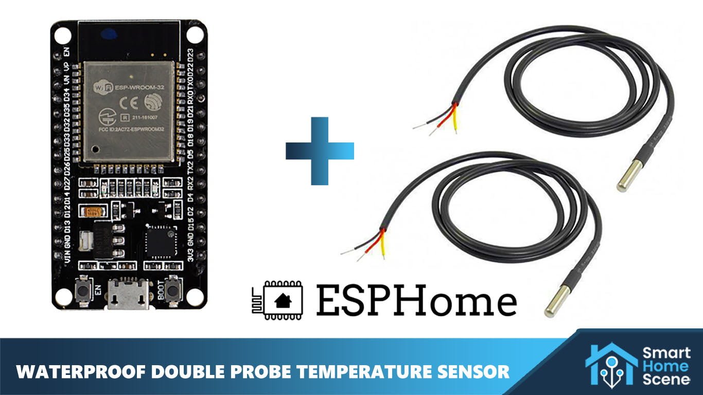
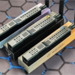
In this how-to guide, I’m going to create a Waterproof Double Temperature Sensor using a single ESP32 board and two Dallas DS18B20 probe sensors and integrate the device in Home Assistant via ESPHome.
Use Cases
Before we go any further, you might wonder why would someone make this kind of a sensor? What would you use it for? In a nutshell, you would use this to monitor temperature in two (or more) different spots near each other on a single ESP board. For example:
- Equipment Temperature Monitor
- Water Heater Temperature Monitor
- Aquarium(s) Temperature Monitor
- Fridge and Freezer Temperature Monitor
- Server Room Temperature Monitor
- Cold Storage Rooms Temperature Monitor
- Whatever else you can think of
In my case, I’ve decided to install the probes in two water tanks which supply hot water in my house. This would enable me to always know the water temp, without a trip to the basement where they are physically located.
Prerequisites
To create this DIY project, there are two ways you can go about it. The first one requires some basic soldering skills, the other can be done without soldering but needs some Dupont wires and is overall a less elegant solution.
I have decided to showcase the no-soldering solution for pure educational purposes. This can be used to test things out initially and useful for beginners to learn. I suggest soldering the components if you intend to install the device as a temperature monitoring gadget.
If you decide to solder the components, you will create a more secure connection between them and eliminate any points of failure. This is the way I recommend of creating this Double Temperature Probe Sensor.
If soldering is absolutely out of your comfort zone, you can achieve the same results by simply pushing the pins inside a couple of Dupont female connectors and securing the wires on the other end with electrical tape. You would also need to obtain a pre-soldered ESP board if you don’t own one.
Here is a shopping list of the required items, some of which you probably already own and can reuse:
🛒 With Soldering:
- ESP32 Board [Amazon, AliExpress] OR
- ESP8266 Board [Amazon, AliExpress]
- Dallas DS18B20 Probes [Amazon, AliExpress]
- 4.7KΩ Resistor [Amazon, AliExpress]
- Soldering Kit [Amazon, AliExpress]
- Heat Shrink Tubes [Amazon, AliExpress] OR
- Electrical Tape [Amazon, AliExpress]
- Micro USB Cable [Amazon, AliExpress]
- Old 5V Phone Charger
🛒 Without Soldering:
- Presoldered ESP32 Board [Amazon, AliExpress] OR
- Presoldered ESP8266 Board [Amazon, AliExpress]
- Dallas DS18B20 Probes [Amazon, AliExpress]
- 4.7KΩ Resistor [Amazon, AliExpress]
- Dupont Wires [Amazon, AliExpress]
- Heat Shrink Tubes [Amazon, AliExpress] OR
- Electrical Tape [Amazon, AliExpress]
- Micro USB Cable [Amazon, AliExpress]
- Old 5V Phone Charger
Note: If you source the components from AliExpress, this DIY project will be much cheaper. Some of the components you probably already have in your home, such as the Micro USB cable, electrical tape and an old phone charger to power the ESP board.
Connecting the Components
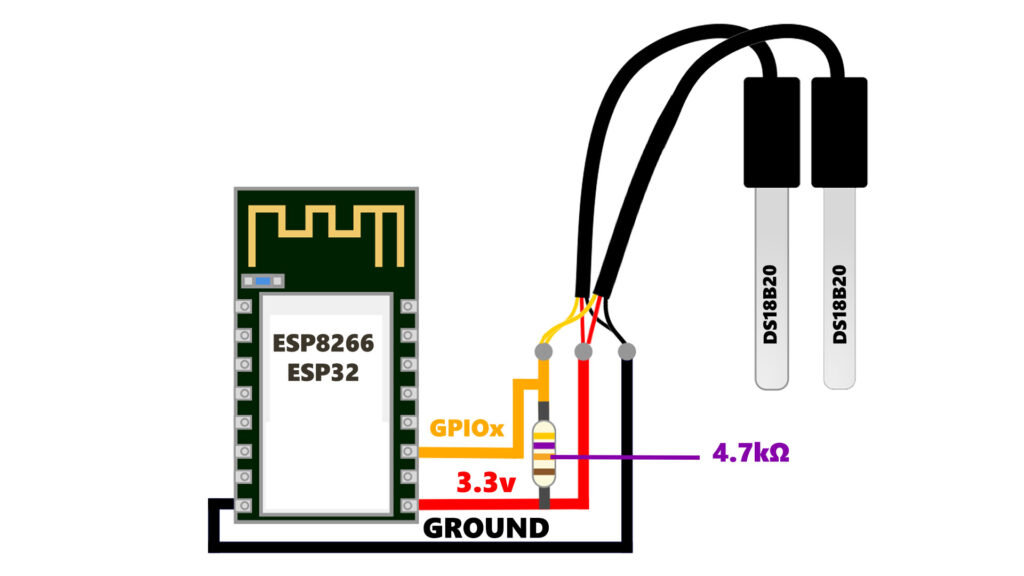
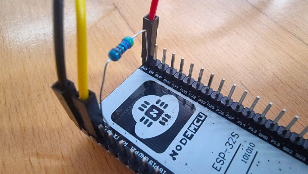
Whether you’ve decided to solder the components or simply connect them with Dupont wires, the wiring diagram is the same. This DIY double probe sensors uses a total of three pins on the ESP board: Ground (GND), 3.3V (Power) and any GPIO pin.
It’s important to understand that different ESP boards will have different labelling on the pins. Here is a board-independent, general wiring diagram showing how to connect two (or more) DS18B20 probes to any ESP8266/ESP32 board.
NOTE: A 4.7kΩ resistor is a requirement for this project and needs to be connected between the data line (GPIOx) and the 3.3v line (VCC).
A quick google search will tell you the pinout for your specific board. For example, the board I am using is NodeMCU ESP-32s which has the following pinout:
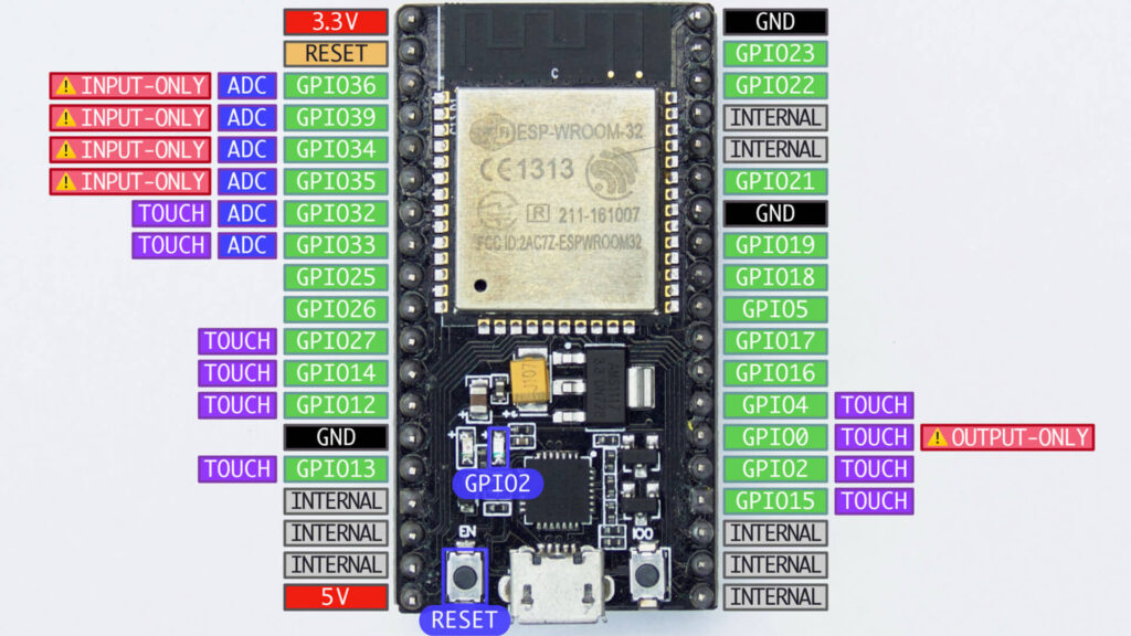
So in my case, I’m going to connect the GND, 3.3v and GPIO22, because the connections would be near each other and easy to do. To attach the components without soldering:
- Push one side of the 4.7kΩ resistor in the female end of the Dupont wire (Yellow)
- Connect (Yellow) Dupont connector along with the resistor to GPIO22 pin
- Push other side of the 4.7kΩ resistor in the female end of the Dupont wire (Red)
- Connect (Red) Dupont connector along with the resistor to 3.3v pin
- Connect (Black) Dupont connector to GND pin
- Connect all wires by color to those of the DS18B20 sensors
- Insulate with electrical tape or heat shrink tubes
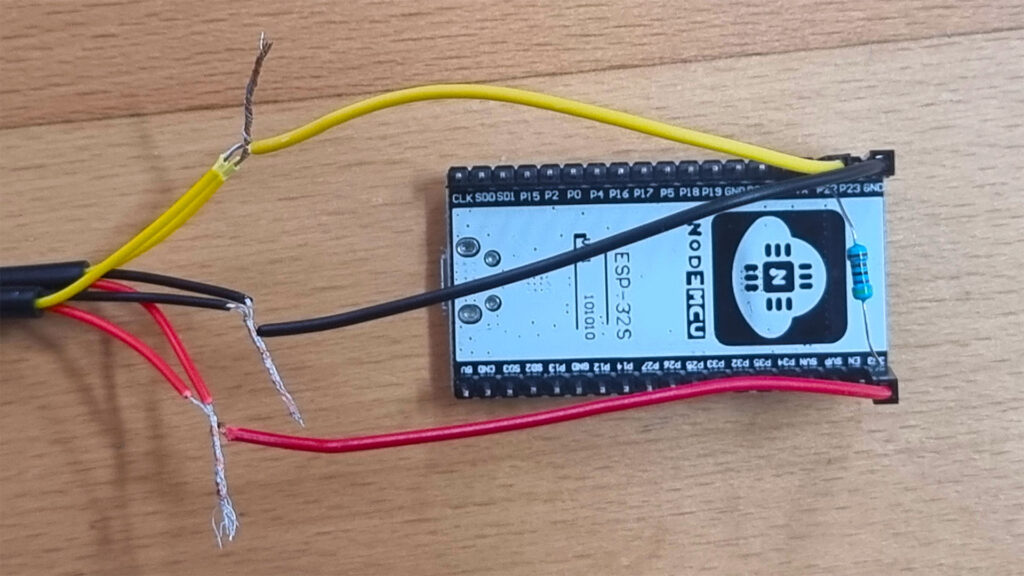
The Dupont connectors will secure the resistor in place and won’t allow any wiggle room. Here’s a closeup of the resistor in place:
Flashing The ESP Board
To setup our DIY Double Temperature Probe Sensor component, we need to initially flash the ESPHome software. There is a couple of way to do this, one of them being connecting the ESP board directly to your Home Assistant server (Raspberry Pi, Intel NUC etc.) via a Micro USB cable:
- Connect your ESP Board to the computer running Home Assistant
- Navigate to the ESPHome Dashboard
- Click the + button in the right corner
- Name your device and input your Wi-Fi Credentials
- Choose the correct device type: ESP32/ESP8266
- Click the three dots under you newly created device
- Select Install
- Select Plug into the computer running ESPHome dashboard
- Select your port and wait for the process to finish
Once you see the logs being populated in the dialog window, it means flashing is completed and you can continue. Click stop to close the popup window.
If you click edit, you will see a basic ESPHome configuration. In my case, I’ve named the device boiler-temperature-sensors:
esphome:
  name: boiler-temperature-sensors

esp32:
  board: esp32dev
  framework:
    type: arduino

# Enable logging
logger:

# Enable Home Assistant API
api:
  encryption:
    key: "ZPhiIaJIWFmDG3kCSD5Oc4K308VIM5T3I+ocXPAIH/w="

ota:
  password: "97c0bd3c5d8f698fc8657f901fb33f4b"

wifi:
  ssid: !secret wifi_ssid
  password: !secret wifi_password

  # Enable fallback hotspot (captive portal) in case wifi connection fails
  ap:
    ssid: "Boiler-Temperature-Sensors"
    password: "VZNUSKQiEHcO"

captive_portal:
Alternatively, you can use the ESPHome Web Dashboard to initially flash the board and subsequently add it to ESPHome in Home Assistant. Its possible you need to hold the boot button while flashing on some ESP boards, the web dashboard will notify you if you do. If you encounter any issues, visit this page.
Adding One-Wire Sensor Config
Once the initial flash is complete, we need to add the 1-wire bus component to the ESPHome code. This will enable us to fetch the address for each of the temperature probes we want to add to our device.
Click Edit and add the following component to your code:
esphome:
  name: boiler-temperature-sensors

esp32:
  board: esp32dev
  framework:
    type: arduino
one_wire:
  - platform: gpio
    pin: GPIO22

 .....
Under the PIN variable, set the appropriate GPIO pin number you’ve used while soldering and assembling the device. Click Save and flash the software again in the same way. Once the process is complete, you will see a list of sensors discovered in the logs of the dialog window:
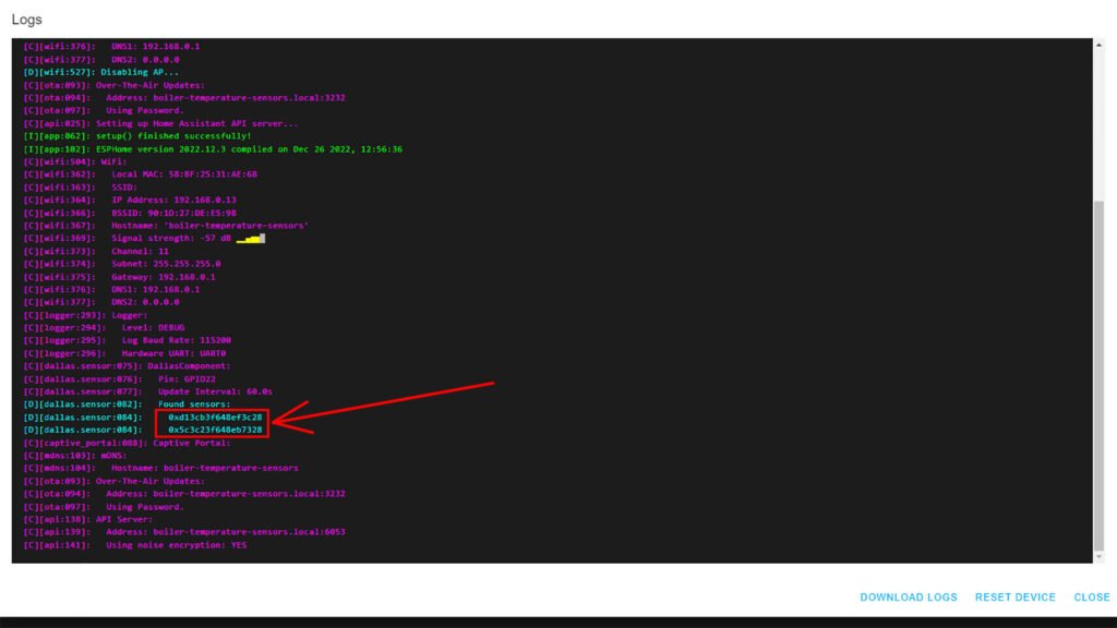
Copy these two addresses and save in a file somewhere for convenience. We will add them to the configuration in the main boiler-temperature-sensors YAML file.
- Click Edit under your device in ESPHome
- Add the following configuration while replacing the addresses with yours
esphome:
  name: boiler-temperature-sensors

esp32:
  board: esp32dev
  framework:
    type: arduino
one_wire:
  - platform: gpio
    pin: GPIO22
sensor:
  - platform: dallas_temp
    address: 0xd13cb3f648ef3c28 #Replace
    name: "Boiler 150l Temperature"
  - platform: dallas_temp
    address: 0x5c3c23f648eb7328 #Replace
name: "Boiler 100l Temperature" - Click Save at top right corner
- Click Install and select Plug into the computer running ESPHome Dashboard
- Wait for the process to finish
- You will receive some temperature readings in the logs:
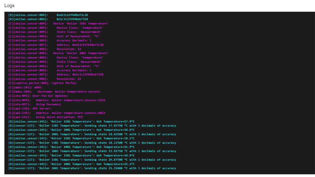
The ESPHome configuration is complete. If you are unsure which address corresponds to which temperature probe, you can hold one with your hand and note the temperature reading increase. Subsequently change the corresponding name in the ESPHome configuration.
Adding Sensor to Home Assistant
Once the device is pushing data to Home Assistant through ESPHome, you will receive a notification “New Devices Discovered”:
- Click Check it out
- Or navigate to Settings > Devices & Services
- Click Configure
- Click Submit
- Optionally add it to a room
- Click Finish
Summary
This Waterproof Double Temperature Probe sensor is a great starting point for smart home enthusiasts who are just scratching the surface of DIY automation with ESPHome.
I’ve set up my sensor probes to monitor hot water temperature of my two boilers in the basement. This will save me a trip or two to the basement and I can automate the heater within Home Assistant based on the readings of the probes.
If you do decide to try this neat DIY project, I suggest going for a Wemos D1 Mini [Amazon, AliExpress] and 3m DS18B20 [Amazon, AliExpress] Dallas probes. The D1 mini is more than capable for this device and the 3 meter long probes will give you some wiggle room when positioning the device. I also strongly recommend you solder the components instead of using Dupont wires.


Why do you have both sensors going to the same GPIO? Why not two GPIO pins so you have independent readings from the sensors?
They are independent readings, this is the way the dallas component works.
https://esphome.io/components/sensor/dallas.html
You add the single GPIO pin to activate the Dallas component/hub and add each sensor as a list.
Quote: “The dallas sensor component (or “hub”) is an internal model that defines which pins the DS18B20 sensors are connected to. This is because with these sensors you can actually connect multiple sensors to a single pin and use them all at once.”
I really love the idea and was triggered by:
Fridge and Freezer Temperature Monitor
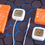
My Aqara sensors tent to quit working after a while, either by loosing the connection to the Zigbee network, or by experiencing too much cold temperature.
Now I was wondering; how did you solve the powering of the sensor when placed within the fridge or freezer?
Actually, the ESP32 is installed outside of the fridge. Only the temperature probes are inside the fridge/freezer.
They have a pretty thin cable, so I managed to squeeze them in the corner of the rubber frame of the door. You need to make sure the door forms a seal though, so be careful.
Cheers
Ah, makes sense! Just ordered at Ali, thanks!
hi there, a great article thanks. You used the word waterproof in the title, what case would you recommend for this project? Thanks
Hello Shaun,
By waterproof, I meant the Dallas Probes are waterproof themselves, I wasn’t referring to the ESP32 board.
You can submerge the probes and they will work without problems, that’s why I suggested getting a longer cable probes, so you can separate the ESP32 comfortably.
Cheers
Hi!
I have only 2 entities, 1 temperature, 1 firmware.
I used it with one sensor before, I just added the second sensor.
What could i have done wrong?
Hello Peter,
I wouldn’t know until I see some code. Use admin@smarthomescene.com
Cheers
Hey there, what a great guide, many thanks for it. I was able to set-up all using my desktop Esp home. The set-up works just fine and is really straight forward. I am going to use it as a water temp. sensor of a jacuzzi outside. Will equip with a battery and charge with solar. I owe you a coffee :).
Hey,
Glad you liked the idea and guide!
Cheers!
hey, nice project – out of curiosity how many sensors could be supported in this setup?
Hey,
A maximum of 8 sensors can be wired to a 1-wire setup like this one.
Cheers
Great tutorial. I completed this but when the resistor is connected, I dont get a reading, if I disconnect the resistor it works fine? Any idea?
You must have a resistor, otherwise the reading will be skewed. Its either faulty or wrongly connected.
Double check the solder/connection points.
I’ve just done this through ESPHome, connected to the 3v pin I can get a maximum of 2 sensors connected. With the 5v pin I can get 3 sensors. Same story as yourself, with resistors connected I get nothing, but without the readings are coming through. I have 6 sensors connected to the board via 3 different hubs. I’ve checked the readings vs an IR temp gun, and they seem to be correct.
From ESPHome:
https://esphome.io/components/sensor/dallas.html
I am well aware, I read this – but googling around you’ll also find numerous cases where people are saying that Dallas was broken with ESPHome in late 2022 and have been waiting for a fix.
I tried in vain connecting all my sensors in a 1-wire setup on both an ESP32 and ESP8266, it didn’t work. With or without resistor. I tried soldering everything together, I tried it all in a breadboard – nothing. I tried adding them 1 at a time with a resistor – nothing. The first time I got any sensor detected was WITHOUT the resistor. So I begun playing around, adding 1 sensor at a time and through trial and error this was what I got to work. 2 Dallas sensors per hub powered by a 3v pin, or 3 Dallas sensors per hub powered by the 5v pin.
Tried on 3 different ESPs of each board, a mix of brand new boards and 3+year old boards – same thing.
I totally understand your argument of “You must have a resistor, otherwise the reading will be skewed.” – however a skewed reading is better than NO reading, which IS the case in my experience. However as said above, I took manual readings with an IR gun, and the temperatures at the probes were within 1degree – which is more than accurate enough for what I need it for.
Excellent feedback, I didn’t realize the Dallas component was borked.
Thank you for sharing your experience Craig, I will pin your comment for other with the same issue.
Cheers
Hello. Tell me, is it possible to add Dallas DS18B20 probe sensors to the sensor zth02, for example?
No, you cannot attach a Dallas probe to a Tuya proprietary sensor.
Worked perfectly. Just wondering if there is a way to reduce power consumption ?
You can experiment with ESPHome’s deep sleep component:
https://esphome.io/components/deep_sleep.html